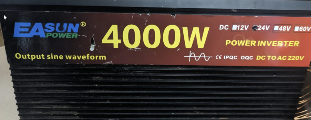
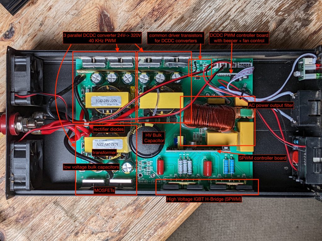
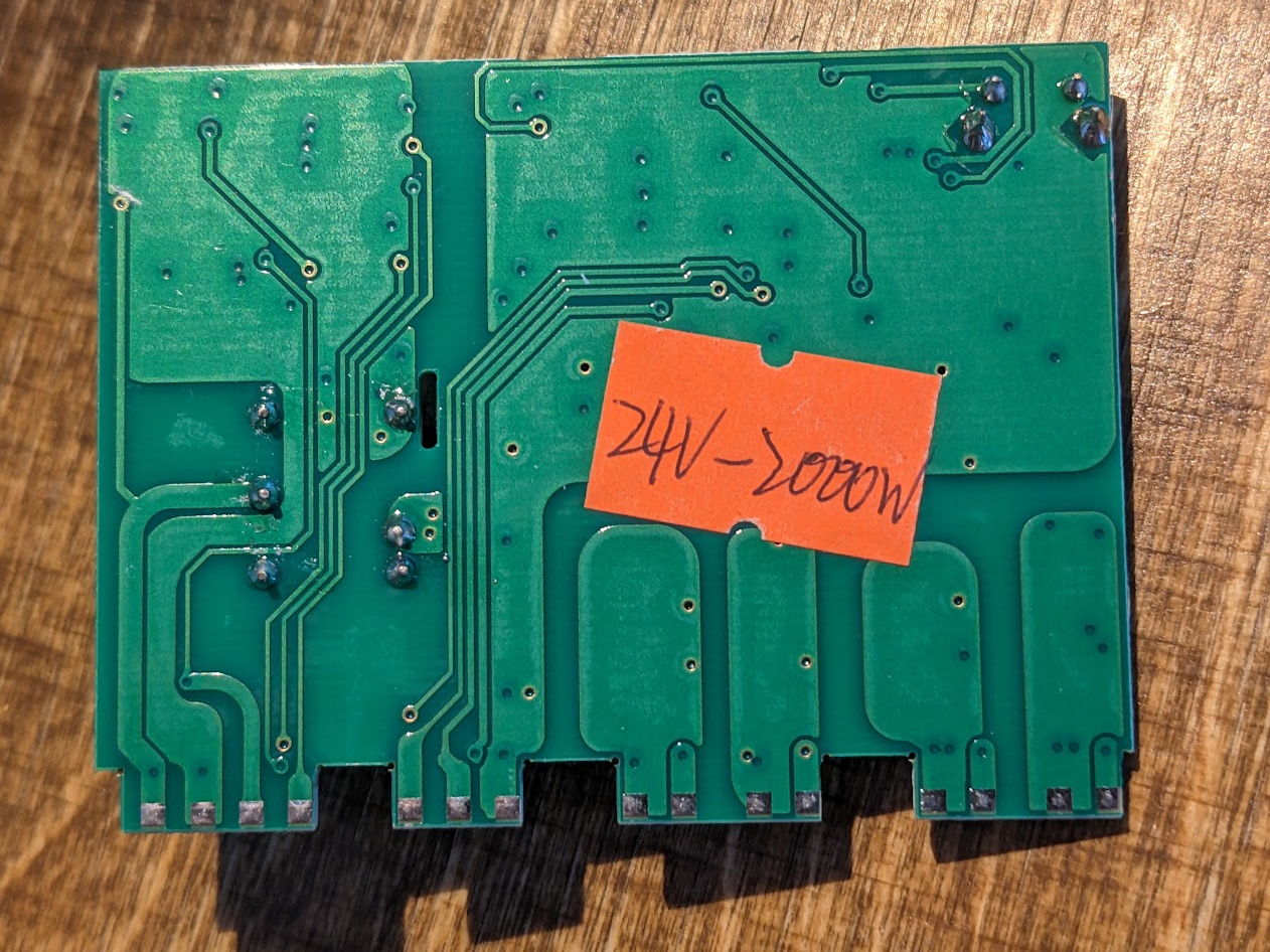
I ordered this inverter from Aliexpress supplier POWLAND Official Store on 2021-06-08 for US $118.22 (Product Link). In September 2022 I ordered a similar from same supplier. It worked quite well for about 6 months, charging my EV with constant 2000W from a 280Ah LiFePo4 battery, until we powered a big truck battery charger and jump start aid. Probably due to the high inductive load one side of the SPWM full bridge IGBTs died, also toasting the drivers.
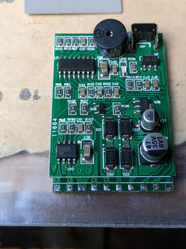
I replaced the drivers and IGBTs, unfortunately I put IGBTs without a body diode, which lead to voltage spikes of 600V and above at the higher IGBT’s source, which finally killed drivers and the SPWM controller. The supplier send me a replacement board for free (only had to place a cheap order at their store). I did not have time yet to finish the repair.
Issues
- DCDC Burst mode causes high current peaks, lower conversion efficiency, EMI and stress for batteries
- Decreasing efficiency above 25.5 V input voltage (see below)
- Inductive loads might toast the SPWM bridge (TODO verify)
- No under voltage recovery
- Fan control by power output, not temperature
DC-DC Mosfet
- FHP4410 pdf
- 140A, 100V, 5.5mΩ(typ), 7.2mΩ(max)
- Qg=150nC, Qgs=30, Qgd=60nC
- Qrr=65
- Vpl=4.2V


Transformers
The transformers are labelled EC42-24V-220V (or EC42-24VF-220V newer?). They consist of a EC42/22/15 Ferrite core (similar to ETD 44/22/15, see TDK EPCOS data book 2013 p527) with a round center leg. I computed the relative magnetic permeability µ_r = 2200. The primary winding is wound between 36 and 26 turns of the secondary winding.
Primary winding
- copper tape 22mm * 0,2mm * 600mm
- 4+4 turns
- wound around inner half (36 turns) of the secondary winding
- 40mOhm, 92uH
Secondary winding
- 0,75mm (AWG 21)
- 36+26=62 turns (inner + outer)
- 2200uH, 200mOhm
Feedback winding
- 2T, 40uH, 50mOhm

Efficiency measurement
I measured conversion efficiency P_out/P_in with a 500W light bulb (resistive load PF=1.0) for varying input voltages. Above 25,5 V, efficiency drops rapidly. This is likely because the DCDCs go into burst mode, causing huge current spikes, increasing losses (P=I² * R). I indicate the average conversion efficiency to be 92 %.


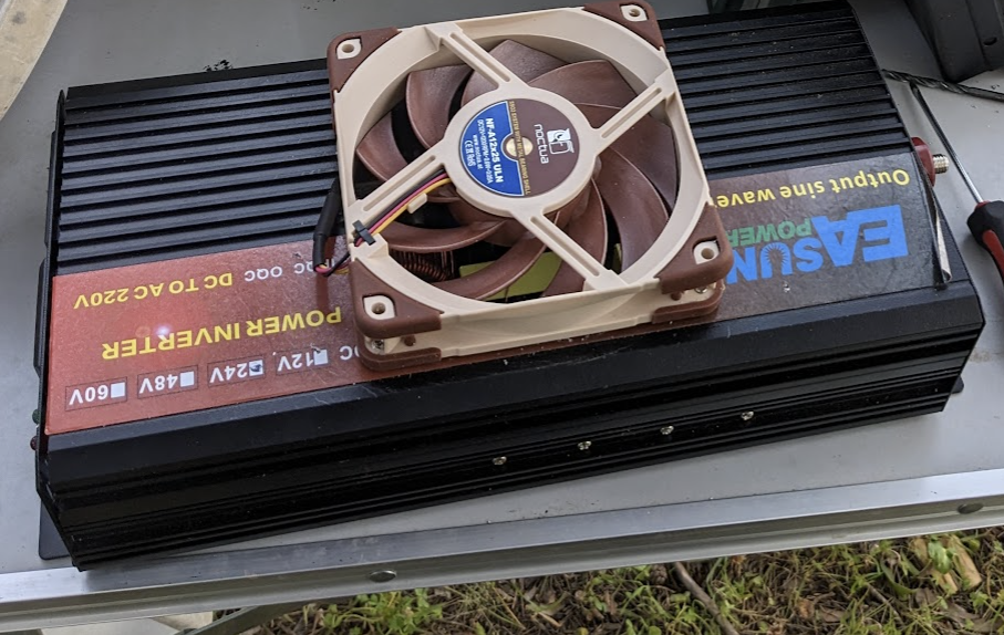
Fan mod
For silent active cooling I sawed a hole in the upper enclosure and put a Noctua NF-A12x25 ULN . I used aluminum tape to seal the gaps around the fan.

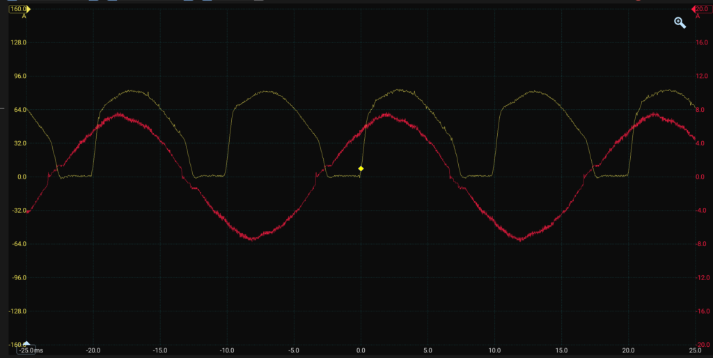
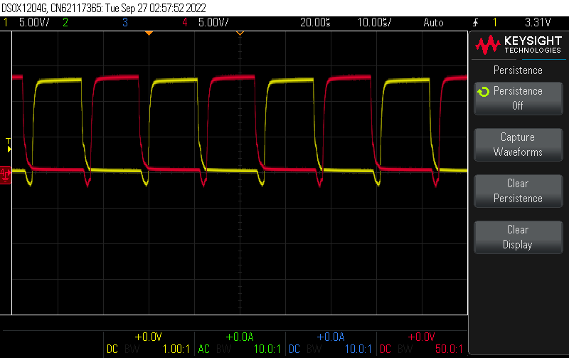
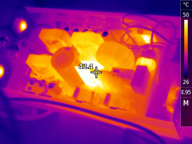
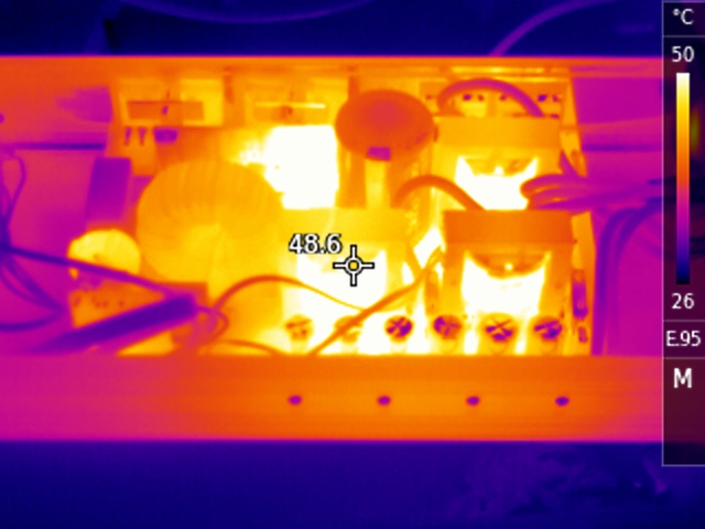
Input Current (yellow, avg=48A) and Output Current (red) @ vin=25.74V pout=1129W RMS, pin=1235 W
tesU/I=5/217
76.9A 25.4= 1953.26 – 1771
66A, 25.5, 1534. 7/210
Idle Ripple Current
Ripple Current
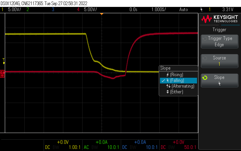
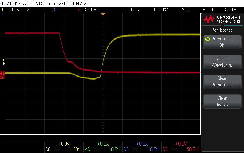
Idle Ripple Current @ 26,3 V
RippleCurrent
I measured the input current with a Riedon SSA-100 and a PicoScope. Note that inverter current consists of DC and AC components. Most consumer current sensors will under-estimated the average current (e.g. Victron SmartShunt) and are not suitable for accurate measurement of efficiency.
Idle @ 26.3 V:
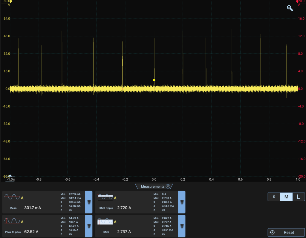
I_average = 320 mA (8.4 W, whichs is quite good)
I_RMS = 2.75 A
I_RMS_ripple = 2.64 A
I_pp = 63.2 A (!)
The peak current is insanly high beyond 60 A. This is due poor voltage regulation ov the secondary 400 V DC. The push-pull converters then act in burst mode. Push-pull converters output voltage is quite fix and hardly to regulate with PWM.
2kW Load:
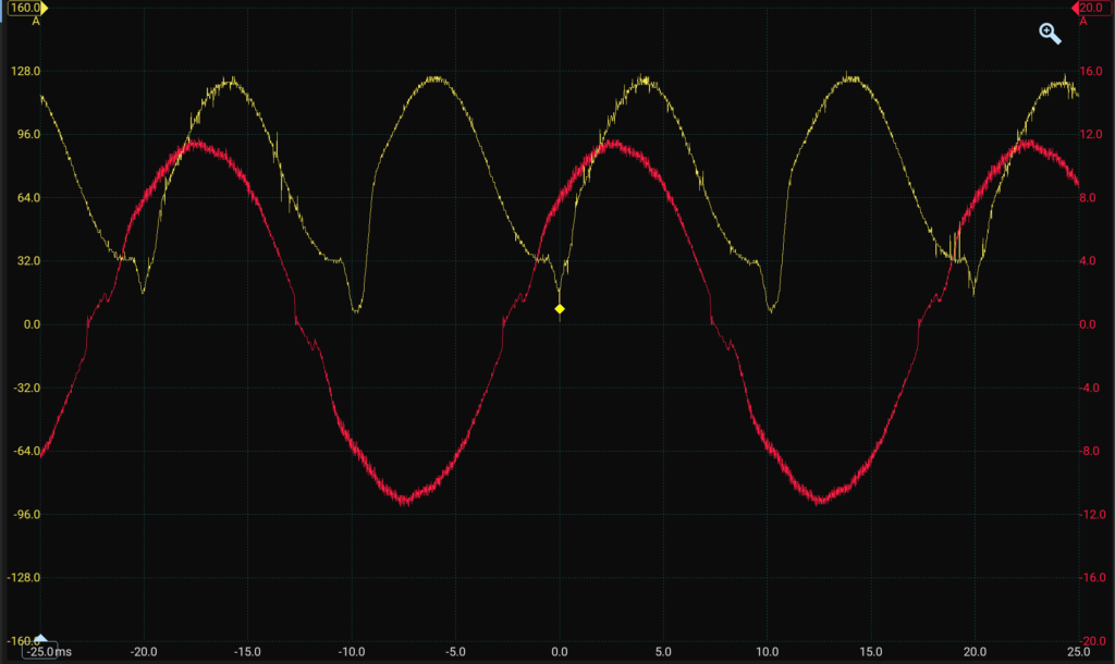
The input current has a dip at the lower half-cycle of the sine wave. The current falls from 32A to about 5 A, follwed by a steep up transient. This can confuse current sensors in e.g. BMS (JK BMS).
SPWM Filter

- inductor
- 2.47mH
- 10khz Rs=270mΩ
- 100khz 2.8mH, Rs=38Ω
- DCR = 78mΩ
- Turns = 92N
- => Core A_L = 295nH
- wire OD=1.35mm ~1.3mm cu?
- Core OD=48mm, ID=18mm, H=19mm
- T184
- µi ~125µ
- MS-184125-2
Conclusion
- very low price (<100$)
- constantly outputs 2kW
- OK efficiency (90-92%)
- sane fan control
- Small dimensions
- EMI, high current transients
- can die from inductive loads
- low average idle current (300 mA) with 60 A peaks!
- doesn’t restart after over-temp, over-power
- there are sellers that supply replacement parts (e.g. the half-bridge driver board)
- good sinusoidal waveform even at full power