Protective Earth Hazard
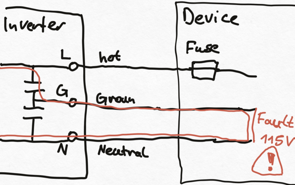
As many cheap inverters from China, it uses a capacitor voltage divider to create a „neutral“ ground. This ground is in fact just centered between the 2 output wires using a capacitive voltage. This poses the problem that current can flow through the ground wire undetected by fuses or other protection components.
The max fault current depends on the chose capacitance of the voltage divider. It can still be safe to operate if current is limited to 20 mA. It provides its purpose of shielding higher frequencies, as the capacitors couple relatively high frequencies with a low impedance to either line. However, all connected devices with metal enclosures connected to PE will oscillate at 50 Hz at some undefined potential. So we should actually ground the PE with a connection to earth (nail in the ground). Ideally the inverter shuts down if we reach 20 mA fault/leakage current. This leakage current can be detected on the ground line. An even safer setup uses an leakage current transformer . The transformer detects any current that doesn’t equally flow through L & N, for example through the isolation inside the inverter (water).
For safe operation, there must be only 2 lines that can deliver power, not a third, even if it is centered between the two others. To fix the issues with the edecoa inverter there are 2 solutions:
- cut the ground wire and just leaving it floating. connect the PE to earth (nail)
- use an ordinary ground fault circuit interrupter for residential use
- Put a nail in the ground or connect to a big metal structure. Putting the ground to either the hot or neutral wire can problem if inverter’s isolation is poor: it can cause dangerous voltage levels above ground on the battery terminals. There is a good explanation of this matter in an Amazon review. Proper inverter design senses small current through the ground wire and shuts down.
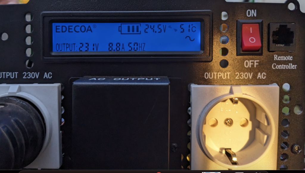
apropos shutdown, this inverter just restarts after over-load or under-voltage situations, without manual reset. This poses a risk of fire in case of bad battery connection or faulty AC loads. Input voltage range is not hard-coded but detected at startup. If we connect a 24V version inverter to 12V, it’ll run at reduced output voltage, and shut down if we increase voltage past 15V. This is nasty.
The manufacturer ships inverters with loose unconnected cable inside.
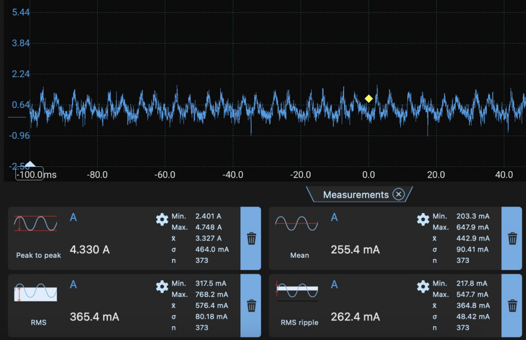
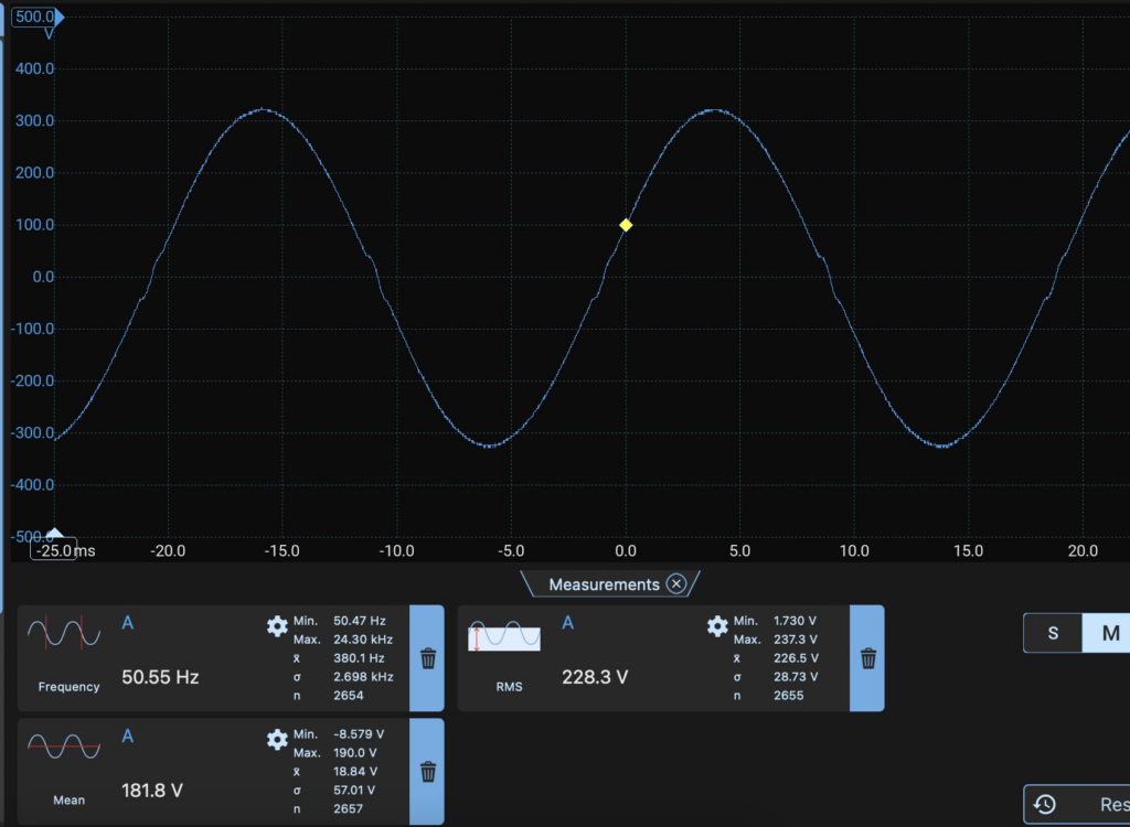
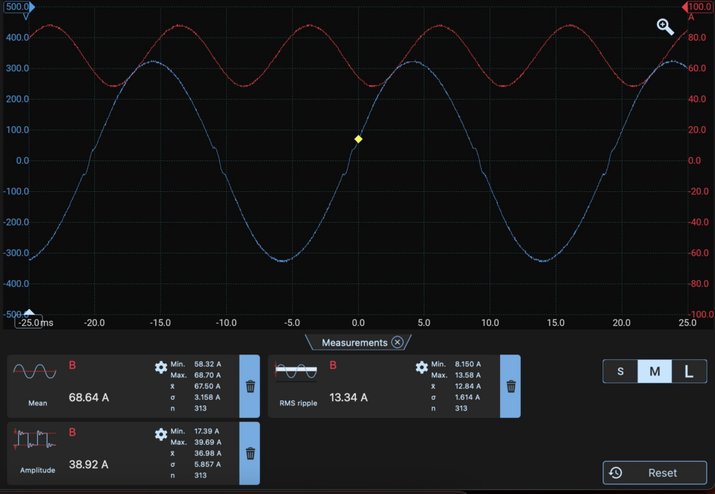
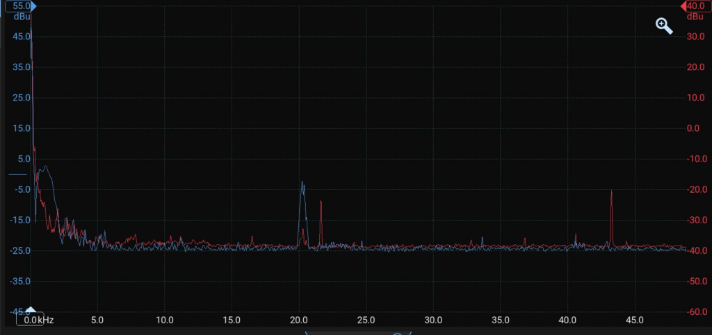
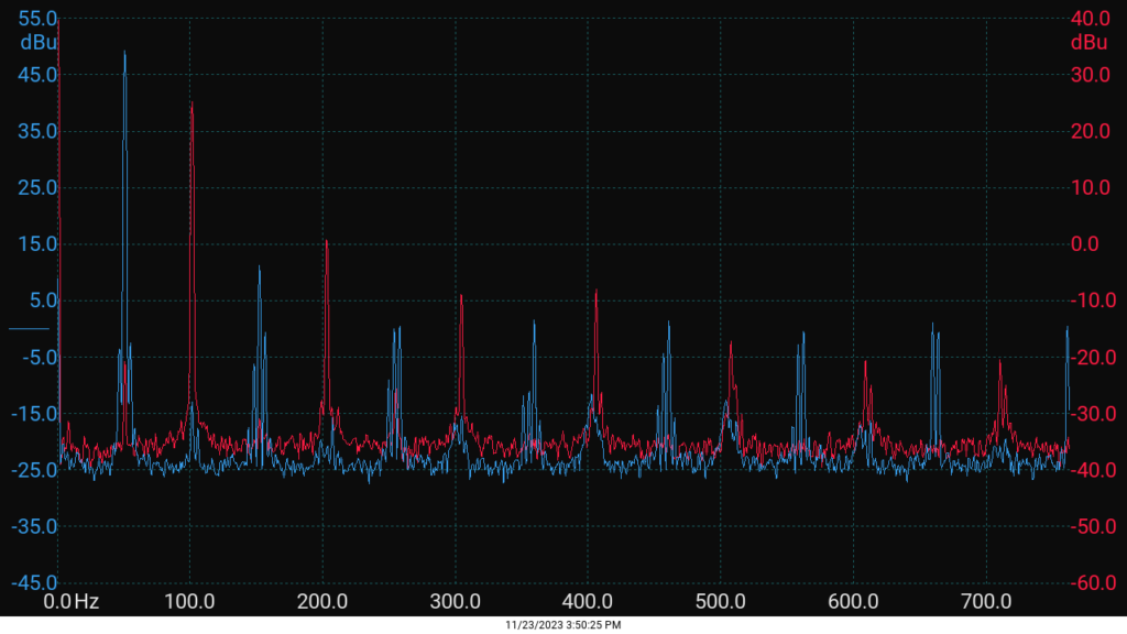
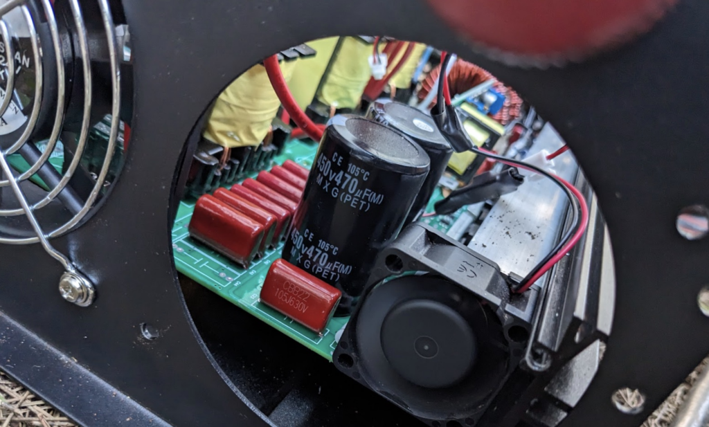
On the upside this device displays output current (althoug with a 10% error), has low input current distortion and a clean output sinus at 3 kW load. The super loud fans are controlled by temperature (on or off), at 1 kW you’ll probably never hear them. They start at a temperature of 45 ºC. Its easy to replace them with quierter ones, note that they run at 24V. They start to spin at 9V already, so maybe just put a small adjustable buck converter in front. Consider flipping the air flow direction so they blow air inside the enclosure through the aluminium heat sinks. All in all it appears to have good efficiency, especially at the primary power switching for transformer drive that runs at 43 (?) kHz.
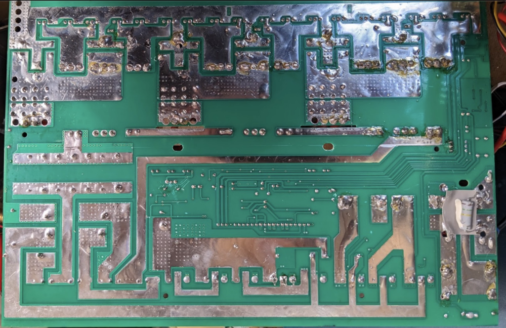
The device I got from a friend displayed „overload“, drawing 10-20W. No output voltage. I opened itand carefully applied voltage with a power supply. The left gate driver on the SPWM IGBT driver board released some smoke. I replaced this EG2113D with an IR2110 (same pinout, some slight differences, see below). I also replaced an IGBT with on onsemi TODO, which appears to do the job quite well. TODO need to test the removed igbt if it is actually broken .
- symmetric ground (earth)
- displays output current and device temp
- temperature controlled fans (2 speeds: on and off)
- very load annoying fans. fans suck air out of the device. install the other way?
- at 7A out they occasionally turn on (17 ºC ambient temp)
- Idle consumption
- 26.3V * 440mA = 11.3 W
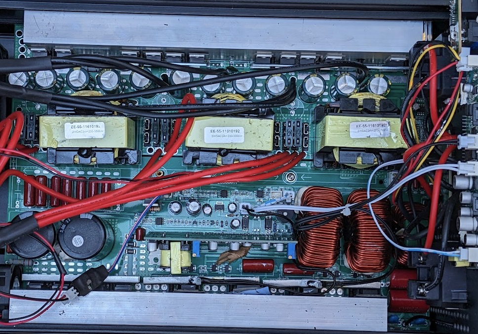
Components
DCDC
Topology: push-pull quasi resonant?
- 3x push-pull converter, each 1167 W nominal
- input caps: 12x 2200uF = 26400uF (35V)
- switches: VS1401ATH
- transformer
- core shape: EE55
- HV rectifier Diodes: 4x FFPF30U60S (600V, 30/180A, 2.1 Vf, trr=90ns, Qrr=360nC) (Fairchild or THINKISEMI)
- HV bulk cap: 2x470uF (450V)
- SPWM IGBT:
- SPWM Drivers: EG2113D (600V, 2A)
- Output Filter:
Pinout SPWM driver board
- V4: Q32 (LS) gate signal (from U2, right driver chip)
- V2: Q21 (LS) gate signal (U3, left driver)
- totem pole N3+P3
- V1: HS gate signal (U3)
- V3: Q17/18 HS gate signal (U2
- G2 Low-side gate drive supply voltage (15V ?)
U3 drives Q21 (LO) and Q19 (HO). Driver IC outputs drive a totem pole through a 1k resistor.
- SPWM gate driver IC EG2113D
- 16 Lead SOIC (Wide Body)
- 600V, 2A
- Vdd 3.3 – 5V
- HIN, LIN, SD inputs
- datasheet shows internal and external boostrapping diode ?
- internal dead-time
- similiar
- IR2113 (600V, 20ns delay match)
- IR2110 (500V, 10ns)
- the IR chips allow up to 20V Vdd
pmset noidle
Silent Fan Hack
At 2kW, the secondary HV rectifier diodes and the IGBT full bridge dissipates most heat. I unplugged the fans and the inverter shutdown due to overheating after half an hour. (17ºC ambient). I placed a small and quiet 12v fan at the heatsink. A small buck converter steps down the voltage to about 9V. The small air flow through the aluminium profile is already enough to keep the inverter running at 8 A output current. The display then shows 52ºC at an ambient temp of 16ºC.
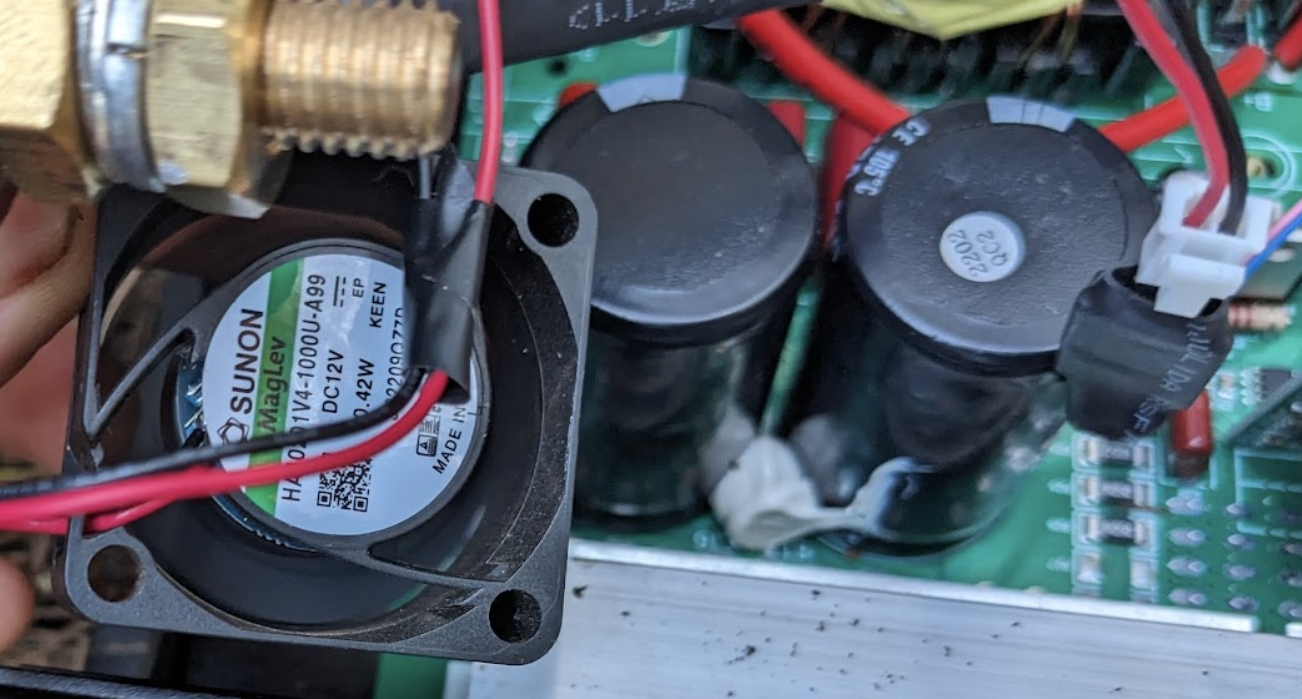
Reversing the air flow direction (with the fans blowing air inside the inverter), appears to make more sense than the original design (fans sucking air out of the enclosure).

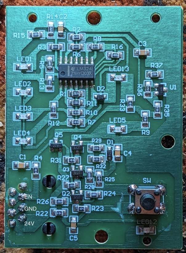
Power Switch Hack
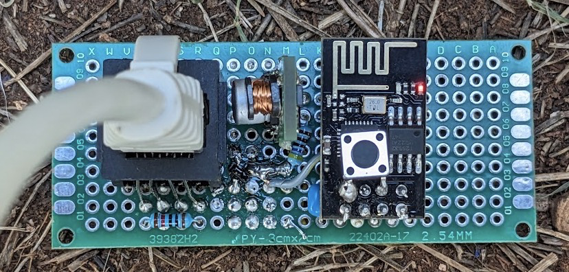
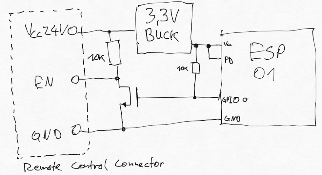
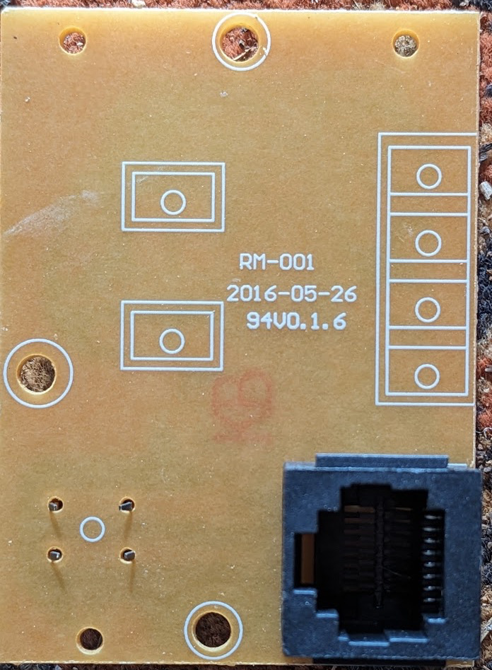
We can control the power switch with a micro controller such as ESP32 and add WiFi, Bluetooth communication. We can then wirelessly turn the inverter on and off. Adding sensors for temperature enables better fan control. A small current transformer to measure output current. Also might want to sense input voltage and a manual reset. Or just capture any fault, and exponential back-off. Need to find a good fault signal source. Whats on the Remote Control connector?
tor at the power input and capture input power. Use a hall sensor for isolated current sensing if needed.