
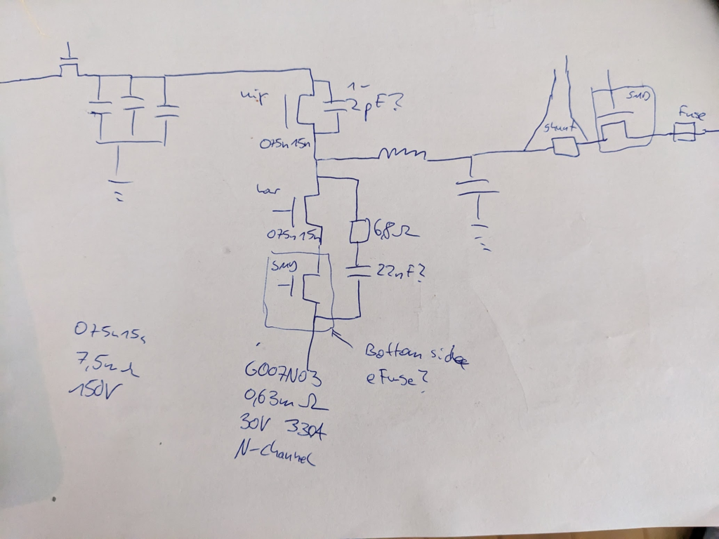
- stm32f103c8t6 mcu
- Switching FETS 075n15n (7,5mΩ, 150V, 2 parallel)
- HYG007N03LS1C2 as low-side protection?
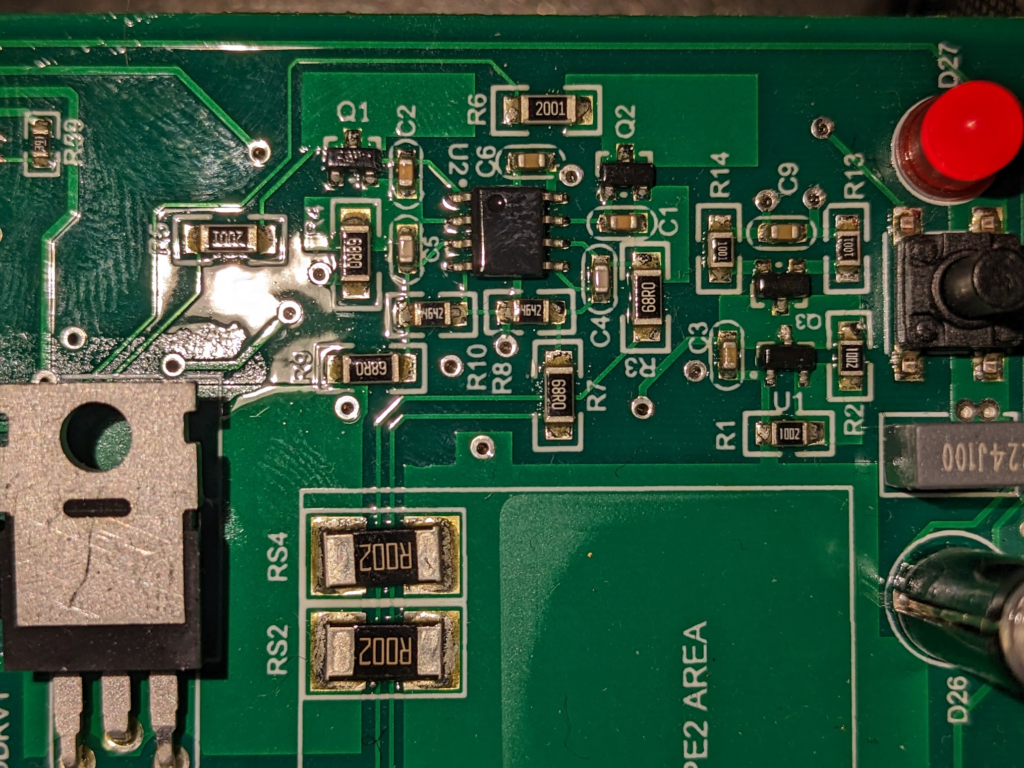
- LMV932ma OP-AMP for current sensing (wires to „shunt“ in the drawing). OP’s Vcc is connected to battery (+). OP Amp V(-) uses some transistor voltage stabilisation (Vcc-5V, source or emitter follower?). The output current at the collector is then flows through a 2k resistor to the MCU ADC pin, which is pulled down with 3.3k, which is the current gain resistor.
- Caps: In: 4x 470uF 160V AISHI HL 105°C 2218JPET

Low-side cascode
By using 2 MOSFET, one high-voltage and one low-voltage in a cascode configuration, we can reduce the reverse recovered charge to the Qrr of the low-voltage device. This will reduce Qrr loss but add additional dead-time loss due to ~2x Vsd. The additional conduction loss is expected to be rather low, if the low-voltage switch has a Rds_on much smaller than the high-voltage switch.
When the HS switch turns on, pulling D high. Now both LS body diodes begin reverse recovery, until the body diode of the low-voltage switch, with the lower Qrr and trr will stop conduction. The HV body diode is still powered at this time and the gate is discharged. The HV fet prevents LV channel break-down.

Paper: Improving the Third Quadrant Operation of Superjunction MOSFETs by Using the Cascode Configuration
Power Measurement
Idle Power: 2.3 W @ 28V
Input: 58V, 4A, 225W
Output: 26.6V, 8.4A, 231W
Loss: 2.69% (eff= 97.3%)
HS Duty Cycle: 45%
Inductor
2 toroidal coils in serial. inner/outer diameter: ~25/~50mm .
turns 15 (or 16?), total 30 (32) turns.
Wire: 2 parallel, 2.25mm diameter
120uH, 10mOhm DC resistance
Gate Drive Characteristics
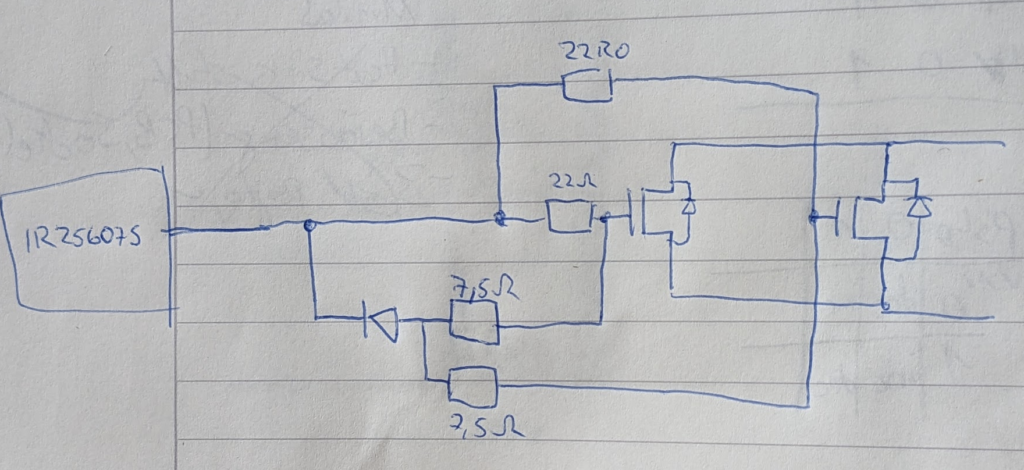
Driver Chip: IR25607S (600V, 2.5A(+)/2.5A(-))
Gate Drive Voltage: 12V
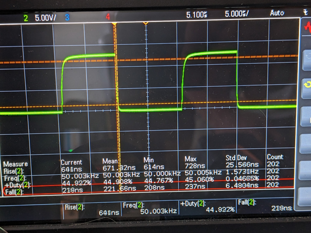
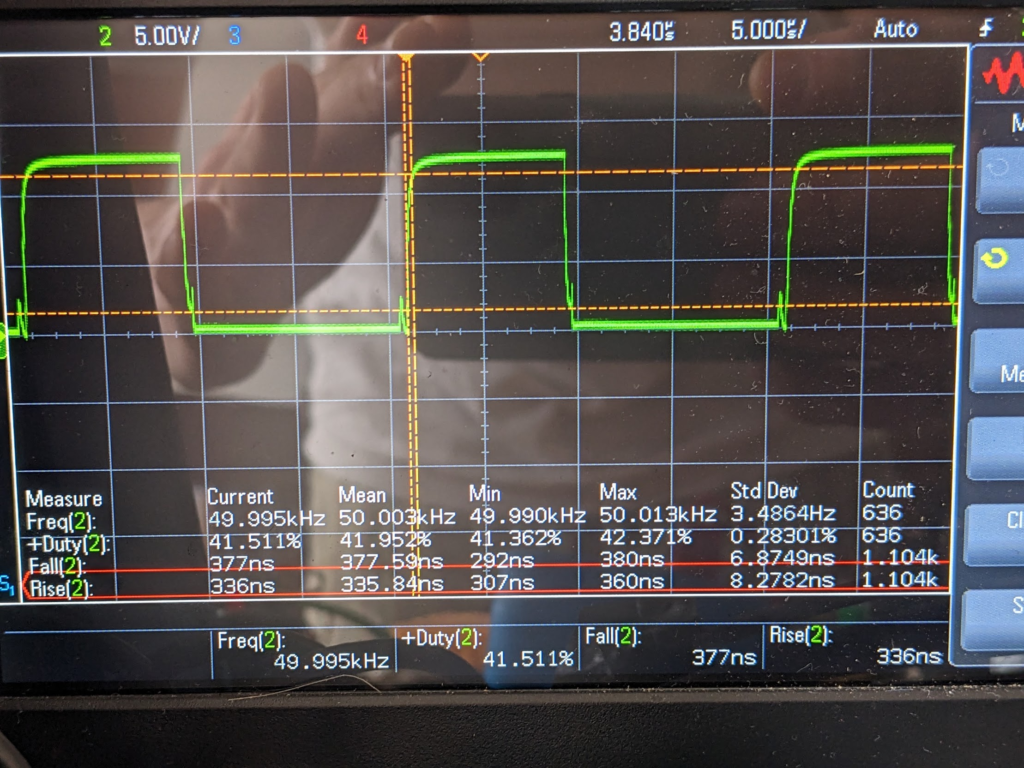
PWM Freq: 50 kHz
Low-Side
Gate Drive R: 7.5ohm (no discharge diode)
Gate Rise Time: 330ns
Gate File Time: 380ns
High Side
Gate Drive R: 22ohm (+) / 7.5ohm (-)
Gate Rise Time: 670 ns
Gate Fall Time: 220 ns
Startup Scan
With input connected to regulated power supply (58V, 16A).

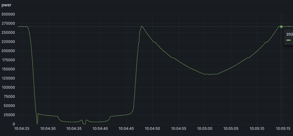
Periodic Scan
every 1h. Takes 49 seconds

Serial Interface
RJ45
1: +V (Battery Voltage) (Green/White)
2: GND (Green)
3: (TX:MATE -> RX:MX/FX) (Orange)
6: (RX:MATE <- TX:MX/FX) (Orange/White)


Outback MATE Reverse Engineering