This is an (unfinished) teardown and analysis of the JK BMS
The JK is a popular BMS among the China BMS (Daly, JBD, ANT), probably because it features an active balancer with balancing currents up to 2 A and the good UX of the iOS App (Android being unable to connect).

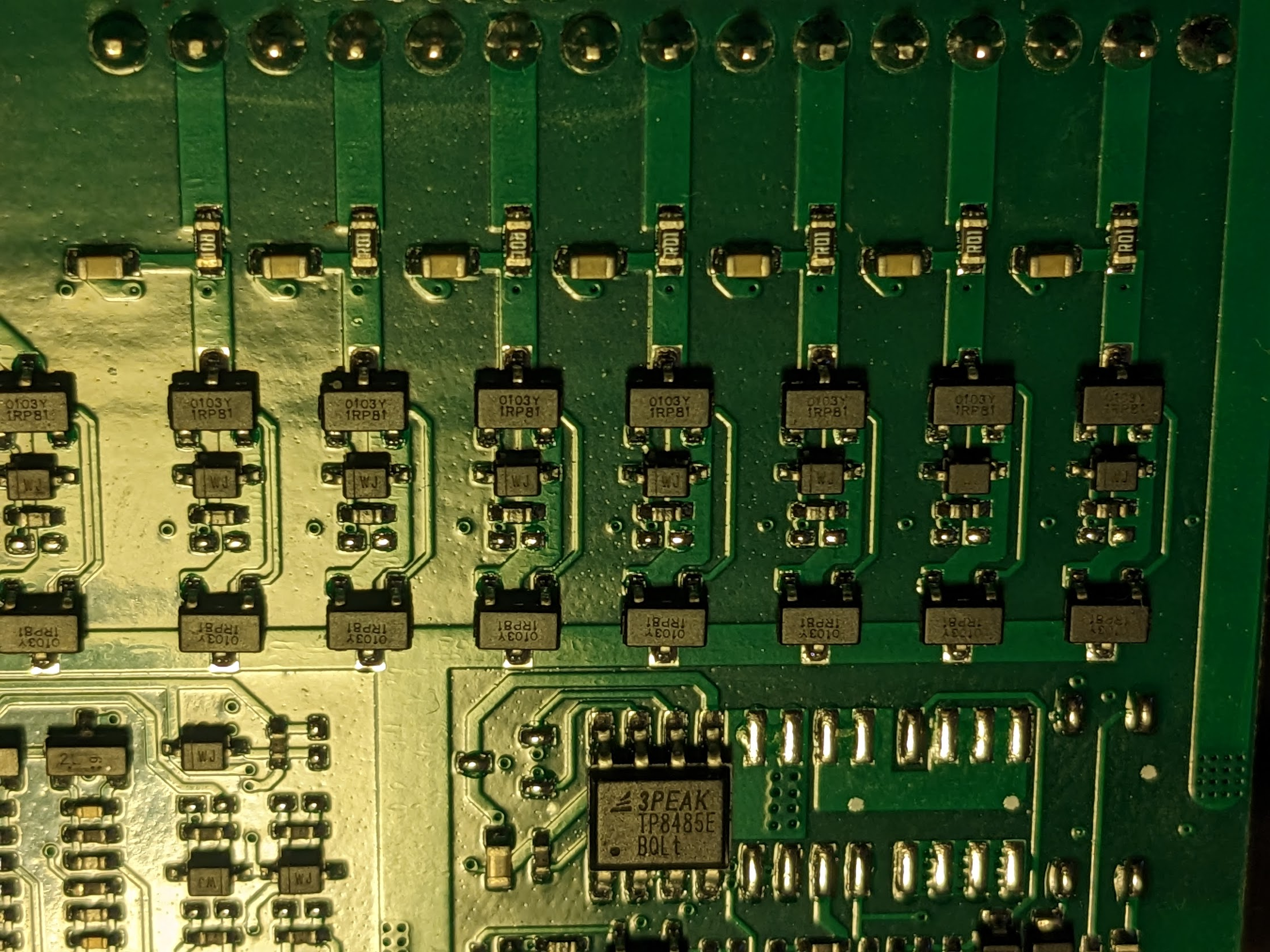
BMS power consumption at 28.55V (no balancing) is 0.61W (~22mA). The LED of the additional power button draws additional 0.05W, totalling 0.66W. With a 100 Ah the BMS will discharge the battery completely in less than half a year (175d), without event running the balancer. (the Daly BMS has a sleep mode to prevent this, TODO need measurement)
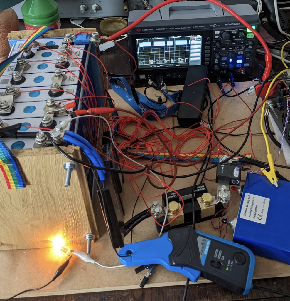
Balancer Test Setup
- JK-BD6A20S10P
- 8x 100Ah LiFePo4
- Oscilloscope & Hantek CC-65 AC/DC current clamp
- 3,55 V external power supply (connected to cell2)
- Light Bulb (connected to cell1, drawing 1.4 A)
- batmon-ha (to capture BMS data)
The light bulb keeps the first cell low and the the power supply keeps the the second cell high, so the balancer only balances between cell 1 & 2. Cell voltage difference almost constant at >~200 mV. Balancing Wire (red) resistance is 45 mOhm.
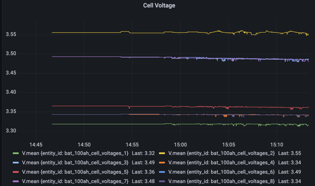
Results
The JK BMS features an active balancer with a single capacitive storage (consisting of 3 SuperCaps each rated 10F 2.7V). The balancing process consists of 2 cycles:
- Negative (discharge): BMS pulls energy from the highest cell into the SuperCap
- Positive (charge): BMS pushes energy from the SuperCap into the lowest cell
These two phases happen interleaved, with cycle periods of a couple of seconds or minutes.

During a phase, the BMS repeatedly checks the cell voltages, pausing the balancing current for 200ms, then balancing for 900ms (making a total 1100ms period). This causes an average duty cycle of 82%. The voltage converter to charge and discharge appears to be working at 60 kHz.


The reported balance current (here it is about 600mA) is somewhat inflated because
- the reduced duty cycle during of balancing / measuring
- 60 kHz ripple of the converter
- since the balance can only either charge or discharge, but not both at the same time, the average current per outlier cell is half of the reported 600 mA (because there are always 2 outlier cells, highest and lowest)
I measured the average current through the wires during a full balance cycle (which was approx 150 seconds) and the average absolute current through the balancer was 390mA (wire2), which is 65% of the reported 600mA (at CellDiff 200mV). So the average balance current of each outlier cell (the highest and the lowest) is about 195 mA, which is less than 1/3 of 600 mA.
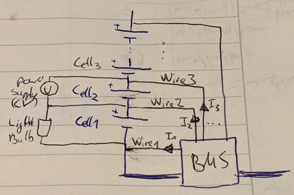
Here are the average measured currents through the balancing wires (direction as in the drawing, pointing from the BMS to the cells)
- Avg I1: -140 mA (charging cell 1)
- Avg I2: +390 mA
- Avg I3: -280 mA (discharging cell 2)
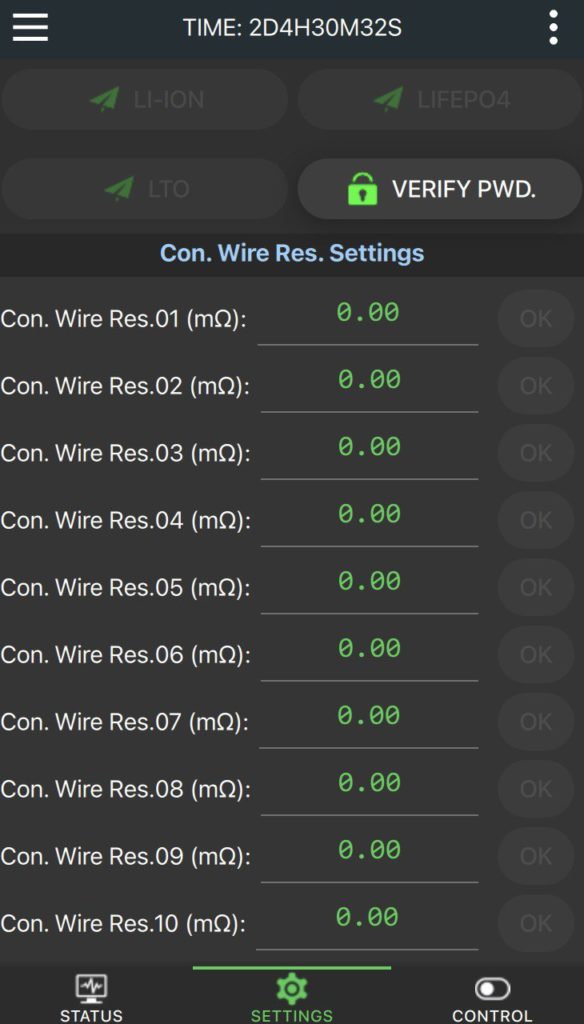
Con. Wire Res. Settings
In the app you can set values for Wire Resistances. At first sight this might be the for telling the BMS about the resistance of the balance wires (the ones that ship with the BMS have 45 mOhm). But it actually means the bus bar resistance, which is much lower. During charge, the BMS will deduct U_wire = I_charge * R_wire from the individual cell voltages. Setting these resistances to higher values than they actually introduces the risk to overcharge. It is always safe to leave them at zero.
